|
History
- Stationary choppers for corn silage date back to the latter
part of the nineteenth century, whereas field choppers, commonly
known as forage harvesters, appeared in the late 1930's.
- The development of machinery for collecting green crops in
the 20 years from the late 1940's to the late 1960's shows
how machines can become obsolete.
- Green-crop loaders which delivered long crops on the front
or rear of a trailer and needed a couple of men with hand
forks to build a load were superseded in some countries by
"one man" loaders and self-emptying trailers; but
it was not long before both of these were replaced by forage
harvesters.
- Of course these are advanced techniques being used in some
countries, but the older ones are also being used in many
places in the world, as a result of different labor and machinery
availability.
 Top
Top
Harvesting
- It is the operation of cutting, picking, plucking digging
or a combination of these operations for removing the crop
from under the ground or above the ground and removing the
useful part of fruits from plants.
Harvesting action can be done by four ways
1. Slicing action with a sharp tool.
2. Tearing action with a rough serrated edge.
3. High velocity single element impact with sharp or dull edge.
4. Two elements scissors type action.
- Manual harvesting involves slicing and tearing action.
Harvesting can be done by
- Manually operated tool
- Animal drawn machine
- Mechanically operated machine.
There are a few related terms in connection with harvesting, which are as below
| Mower |
It is a machine to cut
herb age crops and leave them in swath. |
| Reaper |
It is a machine
to cut grain crops. |
| Reaper binder |
It is a reaper
which cuts the crops and ties them into neat and uniform
sheaves. |
| Swath |
It is the material
as left by the harvesting machine. |
| Sickle |
It is curved
steel blade having a hand grip used for harvesting
by manual power. |
| Windrow |
It is a row
of material formed by combining two or more swaths. |
| Windrower |
It is a machine
to cut crops and deliver them in an uniform manner
in a row. |
Top
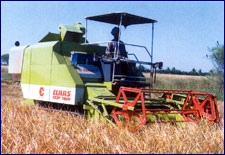
Combine Harvester
- Most grain and seed crops are now harvested with combined
harvester-threshers, commonly known as combines.
- Except for the differences in the feeding arrangement and
the addition of a straw stacker, stationary threshers employ
the same principles and include the same basic components
as combines.
- Although the greatest application of combines is in harvesting
the small grains, corn and soybeans, these machines are also
used for a wide variety of small-acreage or specialty crops.
- Thus, although most emphasis in the following discussion will
be placed upon grain harvesting, occasionally consideration
will be given to other seed crops.
Top
Development history of threshers
- Numerous Biblical references tell how grain has harvested
and threshed by hand.
- The hand reaper was used in Europe and America until horse-drawn
machinery was adopted.
- The long-handled scythe was developed toward the end of the
Colonial period.
- The cradle was introduced between 1776 and 1800. Obed Hussey
obtained a patent on a reaper in 1833.
- McCormick claimed to have demonstrated his first horse-drawn
reaper in 1831 but did not obtain a patent until 1884. NcCormick
built fifty machines in 1845 and about 800 in 1848.
- A platform for manual binding was introduced about 1850 and
the self-raking reaper appeared about 1854.
- The first mechanical wiro-tying mechanism was introduced in
1873.
- Twine binders were introduced in 1880, but it was not until
1892 that
- Apple by obtained a patent on a twine knotter.
- The horse-drawn grain binders were ground driven.
- Auxiliary engines were mounted on some binders about 1920
and the power-take-off-driven binder was introduced in the
late 1920s.
Development of the thresher
- One historian records that in Bedford Conty, Pennsylvania,
grain was still generally threshed with the flail in 1829.
- Much grain was trodden out by horses in the late 1830s.
- The patent granted to Hiram A. and John A. Pitts, December
29, 1837, was the beginning of the thresher. It was horse-operated.
- In 1844, the manufacture of the Case thresher was begun at
Racine, Wisconsin.
- By 1900, threshers were equipped with self-feeders, band cutter
knives, weighers, and wind strawstackers.
Development of the Combine
- A patent on what was termed a combined harvester-thresher
was granted to Samuel Lane in 1828.
- The real beginning of the combine for harvesting, threshing,
and cleaning was when A.Y. Moore et al. of Kalamazoo, Michign,
obtained a patent in 1835.
- By 1854, 600 acres of wheat were combined in Alameda County,
California, but the method was not truly initiated in California
until about 1880.
- One of the earliest manufacturers of horse-drawn traction-driven
combines was the Stockton Combined Harvester and Agricultural
Works of California.
- Steam-tractor drawn combines were introduced in the 1890s.
Some of these machines were equipped with a 42-foot header
and harvested, it was claimed, from 90 to 125 acres in a day.
- Gasoline-tractor drawn combines were introduced on a large
scale in the wheat areas of the Middle West as the result
of labor shortages during the First World War or about 1916.
- Combines were first introduced in northwest Texas in 1919,
when seven machines were used.
- The self-propelled combine was commercially introduced about
1938.
Top
Harvesting and threshing methods
- The systems followed in mechanically harvesting grain
(and other seed crops) include (a) direct combining, (b) windrowing
and combining, (c) binding or heading and stacking, followed
by threshing in a stationary machine, and (d) windrowing,
picking up the windrows with a field chopper, and threshing
in a stationary machine.
- Direct combining and windrow combining require the least amount
of labour, and in the United States, have largely replaced
stationary threshing methods.
- The windrow-combine method involves an extra operation as
compared with direct combining but is advantageous under certain
conditions. Windrowing permits the curing of green weeds and
unevenly ripened crops before threshing.
- The weather hazard to the standing crop is reduced because
windrowing can be started several days earlier than direct
combining.
- Windwors on grain stubble 9 to 12 inches tall cure more rapidly
than standing or shocked grain, regardless of whether or not
rain occurs.
- Heavy vegetative crops, such as alfalfa grown for seed, are
often harvested by the windrow-combine method.
- Stationary threshers are still used to some extent where the
fields are small and the conditions not well suited to combine
operation.
- Binding or heading the grain prior to threshing provides the
advantages of curing green material and reduction of weather
hazards (as with windrowing) but involves a considerable amount
of labour.
- The stationary thresher accumulates the straw in a stack,
which is an advantage if the straw is to be saved for future
use.
- Table 104 given a comparison of the labour to harvest wheat
with various methods.
Top
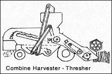
Combined harvester thresher
- It is machine designed for harvesting threshing, separating,
cleaning and collecting grains while moving through the standing
crops.
- Bagging arrangement may be provided with a pick up attachment,
it may be self propelled or tractor operated.
The main function of a combine are:
- Cutting the standing crops
- Feeding the cut crops to threshing unit
- Threshing the crops
- Cleaning the grains from straw
- Collecting the grains in a container.
The whole machine is composed of the following components
- Header
- Reel
- Cutter bar
- Elevator canvas
- Feeder canvas
- Feeding drum
- Threshing drum
- Concave unit
- Fan
- Chauffer sieve
- Grain sieve
- Grain auger
- Tailing auger
- Tail board
- Straw spreader
- Return conveyor
- Shaker
- Grain elevator
- Grain container.
- Header is used to cut and gather the grain and deliver it
to the threshing cylinder.
- The straw is pushed back on the platform by the reel.
- Small combines use scoop type headers, while large combines
use T type headers with auger tables.
- Harvesting is done by a cutting unit, which uses a cutter
bar similar to that of a mower.
- The knife has got serrated edge to prevent the straw from
slipping while in operation.
- There is a suitable cutting platform which is provided with
a reel and a canvas.
- The reel is made of wooden slats which help in feeding the
crops to the cutting platform.
- The reel gets power through suitable gears and shafts.
- The reel revolves in front of the cutter bar, while working
in the field.
- The reel pushes the standing crops towards the cutting bar,
while working in the field.
- The reel pushes the standing crops towards the cutting unit.
- The reels are adjustable up and down as in or out.
- The cutter bar of the combine operates like a cutter bar of
a mower (Fig. 33).
- It cuts the standing crops and pushes them towards the conveyor.
- The conveyor feeds the crop to the cylinder and concave unit.
- Canvas Table conveyors are mostly used with scoop type headers
which have narrow cut.
Top
Paddy thresher
- Paddy thresher is the thresher used for threshing paddy.
- The threshing cylinder is of spike tooth type and the top
cover has louvers to guide the crop axially.
- In the end of the cylinder there is a thrower for the paddy
stalks.
- The thresher has also the cleaning mechanism and bagging attachments.
- It can be operated by a tractor, diesel engine o electric
motor.
- The capacity may be 250-1000 kg/hr.
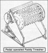
Paddy thresher (Pedal operated)
- It consists mainly of a well balanced cylinder with a
series of threshing teeth fixed on wooden slats.
- It has got gear drive mechanism to transmit power. While he
cylinder is kept in rotary motion at high speed, the paddy
bundles of suitable sizes are applied to the teeth (Fig. 32).
- The grains are separated by the combing as well as by hammering
action of the threshing teeth.
- This thresher mainly consists of: (i) Body frame (ii) Cylinder
(iii) Drive mechanism (iv) Axle.
| (I) Body frame |
- The body frame of the paddy thresher consists of the
base, the side frame, the front grain shield and rear
grain shield
|
| Base |
- The base may be made of mild steel angle section or
of wood. It is suitably fixed to the side frame of
the body.
|
| Side frame |
- The side frame supports side boards which are usually
made of mild steel sheet.
|
| Front grain
shield |
- The front grain shield is made of wooden plank of
about 12 mm thickness and is fitted suitable to the
side frames.
|
| (II) Cylinder |
- The cylinder may be in two sizes.
- One size is about 450 mm in length when the thresher
is operated by one man.
- The other size is 700 mm in length when it is to be
operated by two persons.
- The cylinder has slats, cylinder end disc and threshing
teeth.
|
| Slat |
- Each wooden slat is fixed to the cylinder end discs
by mortise and tenon joints.
|
| Cylinder end
disc |
- The cylinder end disc may be webbed in order tot reinforce
them.
- There are mild steel bars, rolled or welded among
the edges of the disc.
|
| Threshing teeth |
- Threshing teeth are fixed to the slats.
- They are curved in shape.
- The threshing teeth project out above the surface
of the slats to a suitable height.
|
| (III) Drive
mechanism |
- The drive of the pedal thresher is of eccentric type.
- Drive consists of a crank, one end of which is connected
to a spur gear.
- The other end of the crank is connected suitably to
the pedal frame fulcrum, which is welded to the pedal
frame.
- The normal operating speed is about 400 revolutions
per minute.
|
| Gear housing |
- Gear housing is made of cast iron.
- It consists of suitable spur gear which engages the
pinion for transmitting power.
|
| Crank |
- The crank is made of mild steel bar.
|
| Pedal frame
fulcrum |
- It is made of mild steel flat.
|
| Pedal board |
- The pedal board is made of wooden plank.
|
| (IV) Axle |
- The cylinder axle and the gear stub axle are made
of mild steel round bar.
- The axle is supported by bearing with loose balls
in cup and cones and is protected by suitable guards.
|
Top
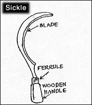
Sickle
- Sickle is a simple harvesting tool.
- It is used for harvesting crops and cutting other vegetations
(Fig. 31).
- It essentially consists of a metallic blade and a wooden handle.
- Sickles are classified into two classes: (i) Plain and (ii)
Serrated.
- Blade is the main metallic part of the sickle.
- It is desirable to make the blade made of carbon steel.
- The blade is made in a curved shape.
- The teeth of serrated sickle is made sharp for efficient working
in the field.
- The handle of the sickle is made of well seasoned wood.
- The forged end of the blade for fixing the handle is called
tang.
- The plain or serrated edge in the inner side of the blade
is called tang.
- The plain or serrated edge in the inner side of the blade
is called cutting edge.
- Protective metallic bush fitted at the junction of the blade
and the handle to keep the tang tight in the handle is called
ferrule.
- Harvesting by sickle is a very slow and labour consuming device.
Top
|